Crystal structure of human U1 snRNP, a small nuclear ribonucleoprotein particle, reveals the mechanism of 5′ splice site recognition
- MRC Laboratory of Molecular Biology, United Kingdom
Figures
Figure 1 with 2 supplements
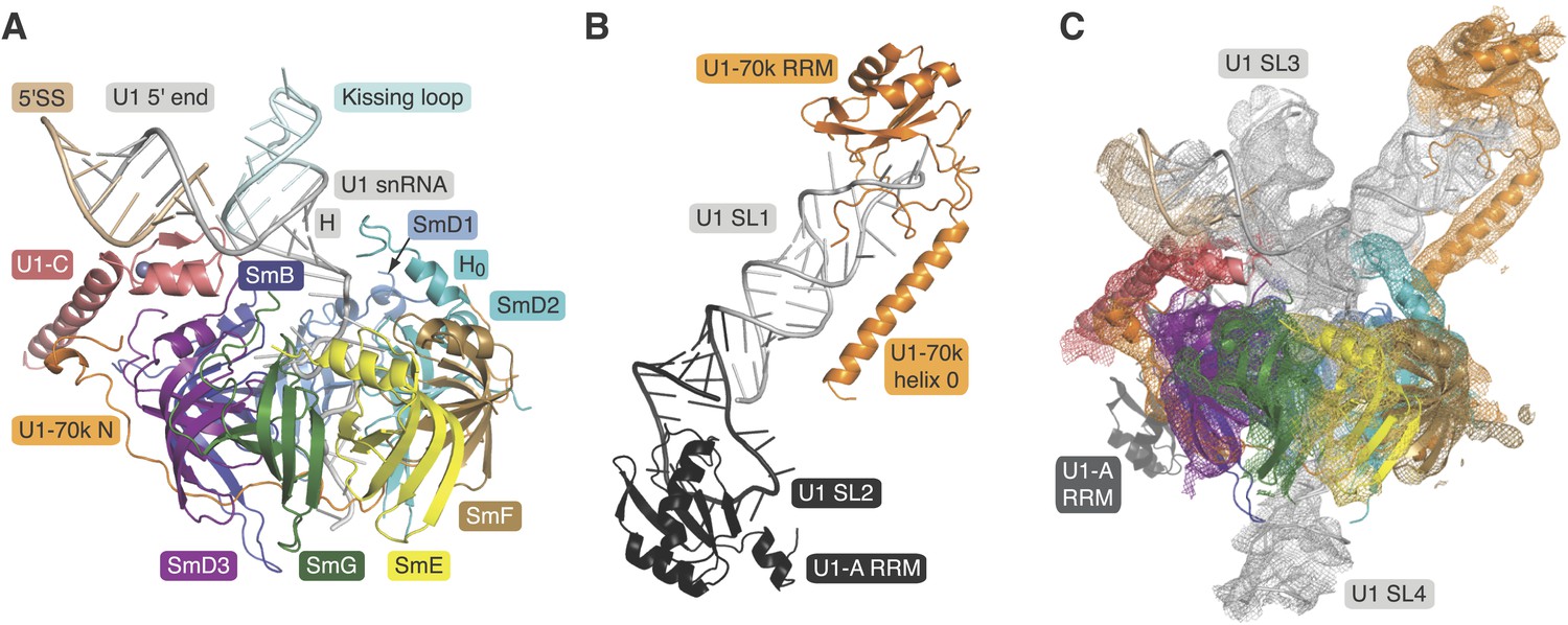
Crystal structures of the two sub-structures of U1 snRNP.
(A) Crystal structure of the minimal U1 snRNP with the 5′-splice site RNA determined at 3.3 Å resolution. Label H indicates U1 snRNA helix H; H0 indicates the first alpha helix of SmD2 protein. (B) Crystal structure (U1A70kF-RNA) of the remainder of U1-70k (residue 60–216) bound to stem-loop I of U1 snRNA determined at 2.5 Å resolution. RRM1 of U1A is fused to the residues 60–216 of U1-70k via Gly–Ser linker. Stem-loops I and II of U1 snRNA form a dumb-bell structure. (C) Crystal structures of the two sub-structures placed into the experimental electron density map at 5.5 Å of U1 snRNP (Pomeranz Krummel et al., 2009).
Figure 1—figure supplement 1
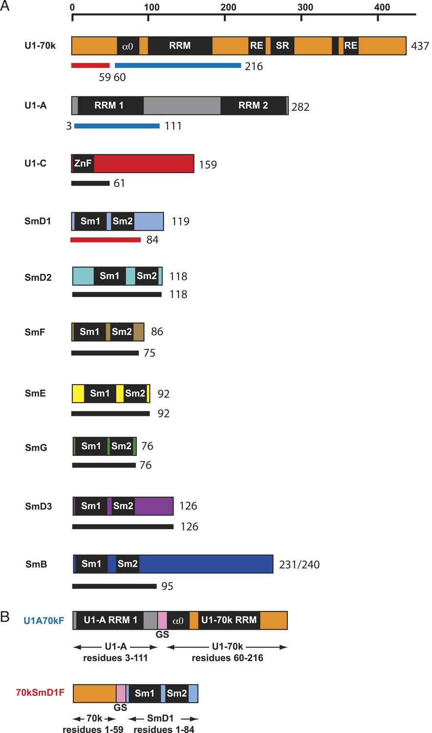
Protein constructs used in this study.
(A) The schematic diagram of the domain architecture of U1 snRNP proteins is shown with horizontal bars. The thinner lines below the bars represent the constructs used for crystallization: blue lines for sequences used in the U1A70kF fusion protein, red lines for sequences used in the 70kSmD1F fusion protein, and black lines indicate the extent of protein constructs used in minimal U1 crystallisation. For binding assays, U1 snRNP was reconstituted with full-length proteins except U1-70k (2–216) and SmB (1–174). (B) The fusion protein constructs were designed using a (Gly–Ser) linker (GS, pink). U1A70kF is used for the determination of U1-70k (60–216) fragment with Stem-loop I RNA. 70kSmD1F is used for the minimal U1 snRNP domain crystallization.
Figure 1—figure supplement 2
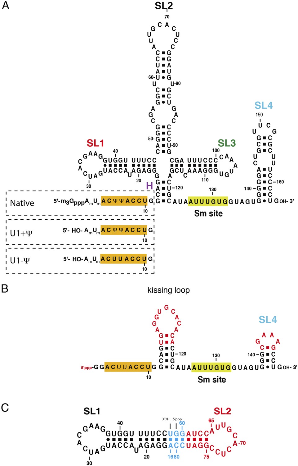
The U1 snRNA constructs used for this work.
(A) Full-length U1 snRNA is used for in vitro reconstitution and further biochemical experiments. Sequences within dashed rectangles indicate the 5′-end variations of U1 snRNA used in biochemical experiments. U1 + Ψ construct contains both 2′-O-methyl groups on A1 and U2 as well as pseudo-uridines at position 5 and 6. U1 − Ψ construct has 2′-O-methyl modifications, but has normal uridines instead of pseudo-uridines. (B) The minimal U1 snRNA (SmKCm) construct replaces the 4-way junction with a kissing loop. (C) In SL1·SL2 RNA, the apical region of stem-loop 2 (U1 snRNA nucleotides 61–78) is shown in red, stem-loop 1 (U1 snRNA nucleotides 17–47) in black and other nucleotides are shown in cyan. Bases in stem-loop 1 and 2 are numbered as in natural human U1 snRNA.
Figure 2 with 2 supplements
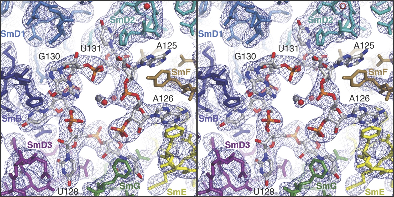
Stereoview showing binding of U1 snRNA at the central hole of the Sm protein assembly.
The refined model is overlaid onto the 3.3 Å electron density map (2Fo − Fc) contoured at 1.5σ. Electron density for A125 and the phenol ring of SmF Y39, which stacks on it, is weak. Hydrated magnesium ion is found in the central hole (grey, Mg++; red, water). SmD3, purple; SmB, dark blue; SmD1, blue; SmD2, cyan; SmF, brown; SmE, yellow; SmG, green.
Figure 2—figure supplement 1
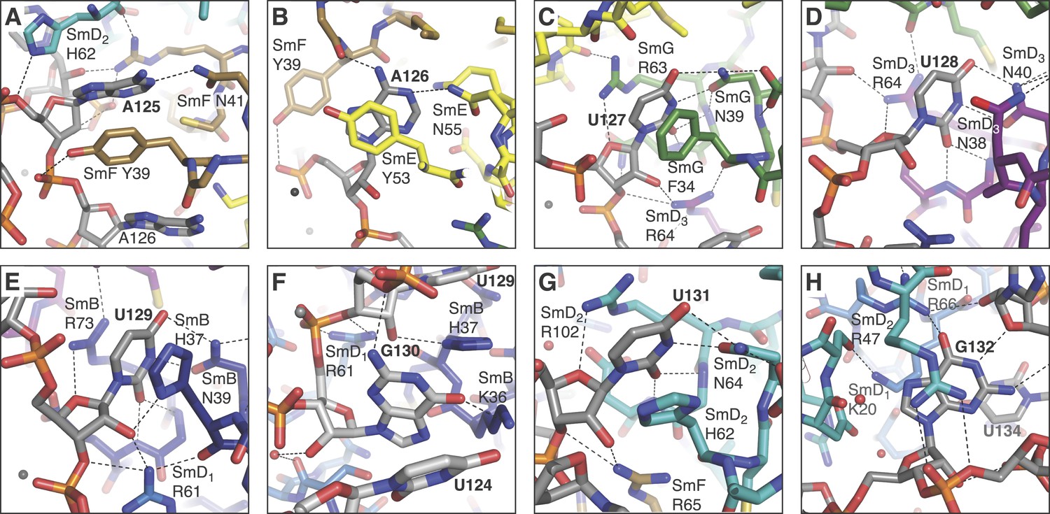
Interaction between the Sm site nucleotides and Sm proteins in the central hole of the Sm protein assembly.
(A), A125. The U2 snRNA Sm site has a guanine at this position. SmD2 His62 and SmF Tyr39 and Asn41 are all loop 3 (L3) residues of their respective proteins; (B), A126 is contacted by SmE L3 residues Tyr53 and Asn55; (C), U127 binding pocket comprises SmG L3 residues Phe34 and Asn39, and loop 5 (L5) residue Arg63; (D), U128 stacks between SmD3 L3 residue Asn38 and L5 residue Arg64, and also contacts L3 residue Asn40; (E), U129 binds in a pocket formed from SmB L3 residues His37 and Asn39, and L5 residue Arg73; (F), G130 is too large to fit in a binding pocket the same way as the other U1 Sm site nucleotides and lies above U124. Its purine base contacts SmB L3 residue Lys36. The nucleotide corresponding to G130 is a U in the U4 snRNA Sm site, which is accommodated into the nucleotide binding pocket in SmD1 (Leung et al., 2011); (G), U131 base is accommodated in a pocket consisting of SmD2 L3 residues His62 and Asn64, and L5 residue Arg102; (H), G132 makes several interactions with the ribose phosphate backbone of neighbouring nucleotides. It does not interact with ‘key residues’ but stacks between the side-chains of SmD2 loop 2 (L2) residue Arg47 and SmD1 L2 residue Lys20, and contacts SmD1 β5 residue Arg66. The nucleotides equivalent to A126 and G132 were misplaced in the original U4 core snRNP structure (Leung et al., 2011) but show interactions similar to those observed here after further refinement (Li J, Leung AKW, CJO, YK and KN, manuscript in preparation).
Figure 2—figure supplement 2

The nucleotides G132, G133 and U134 in the central hole of the Sm protein assembly.
https://doi.org/10.7554/eLife.04986.009
Figure 3
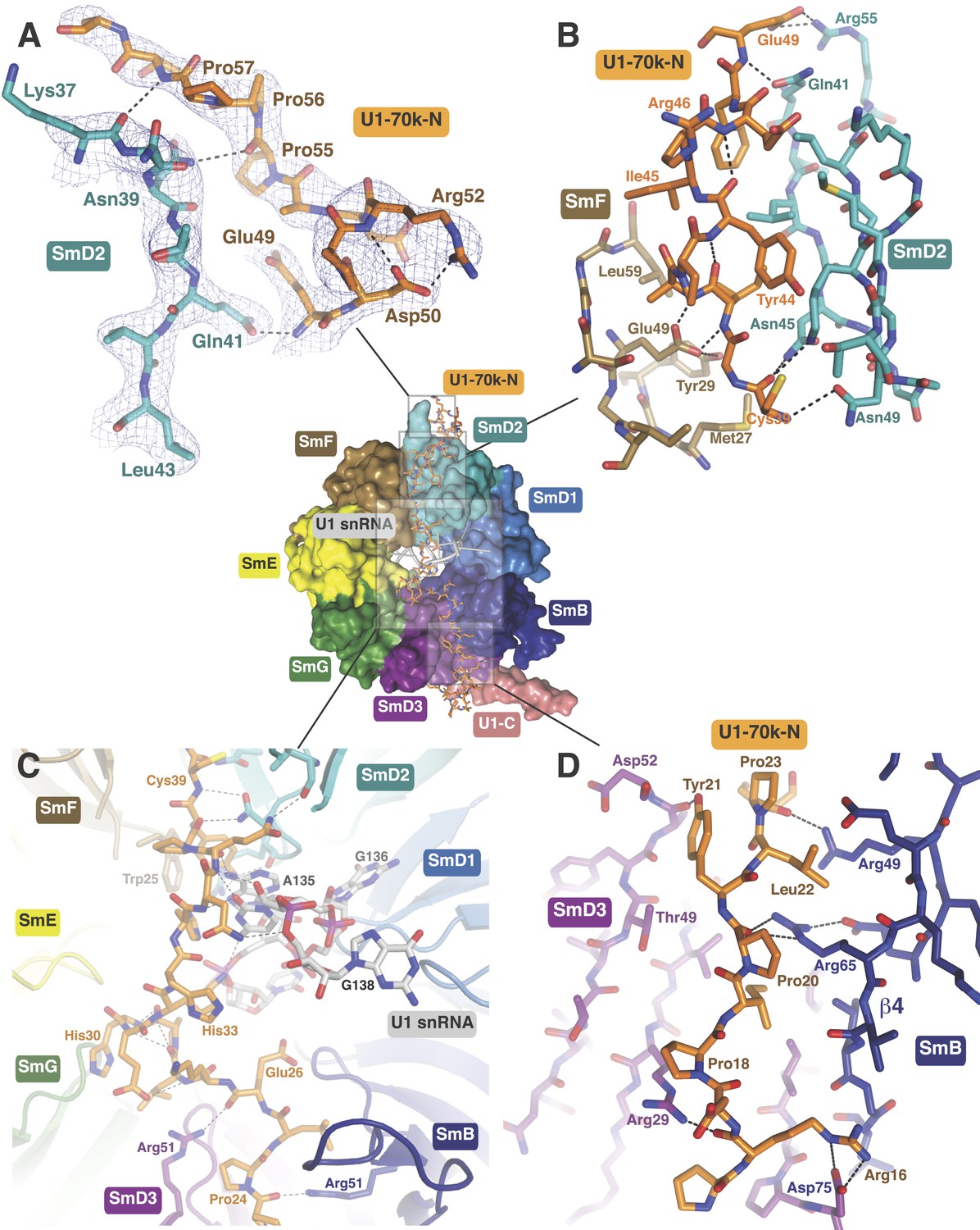
The path of the N-terminal peptide of U1-70k.
The N-terminal 60 residues of U1-70k run along the interface between SmD2 and SmF, cross the central hole and are wedged between SmB and SmD3 (Inset shows the overview). (A) Residues 50–58 interact with loop 1 and β1 of SmD2. Three consecutive Proline residues (Pro54–Pro56) form type II proline helix. (B) Residues 39–49 of U1-70k are wedged between SmF and SmD2. (C) The U1-70k peptide crosses the central hole where it interacts with nucleotides preceding stem-loop IV. In U4 snRNP the 3′ helix is partially buried in the central hole and hence U4 snRNA and U1-70k peptide are mutually exclusive (Leung et al., 2011). (D) Residues 16–23 of U1-70k are wedged between SmD3 and SmB.
Figure 4
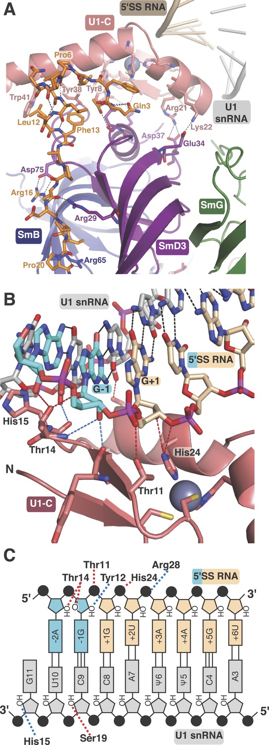
U1-C contacts the duplex between the 5′-end of U1 snRNA and the 5′-splice site.
(A) U1-C sits on SmD3 and its binding is stabilised by the N-terminus of U1-70k. (B) U1-C forms hydrogen bonds with the sugar-phosphate backbone atoms but makes no contact with RNA bases. On the 5′SS strand, nucleotides are colored teal for exonic and fawn for intronic sequence. (C) Schematic representation of the 5′-splice site recognition. Red dotted lines, hydrogen bonds made by amino acid side chains of U1-C; blue dotted lines, hydrogen bonds made by main chain atoms of U1-C. The 5′SS nucleotides are color-coded as in panel B.
Figure 5
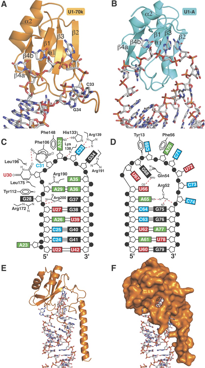
RRMs of U1-A and U1-70k show distinct recognition modes of stem-loop I and II.
(A) Interaction of stem-loop I with U1-70k RRM. (B) Interaction of stem-loop II with U1-A RRM. (C) Schematic representation of RNA-protein contacts between U1-70k RRM and stem-loop I of U1 snRNA. (D) Schematic representation of detailed RNA-protein contacts between U1-A RRM and stem-loop II. (E) Regions of U1-70k flanking the RRM folds onto RNA loop and make extensive contacts with RNA. (F) Apical loop I is completely covered by U1-70k.
Figure 6
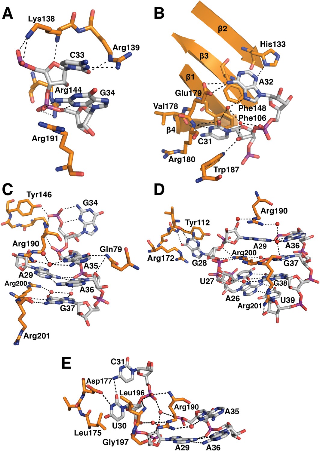
Detailed RNA-protein contacts between U1-70k RRM and stem-loop I of U1 snRNA.
(A) C33 and G34 embraced by U1-70k loop 3. (B) C31 and A32 stack onto Phe106 and Phe148 residues of the beta sheet. (C) The last three loop nucleotides stack continuously on G38 of the loop-closing base pair. (D) The base of G28 is flipped out from the RNA helix and its place is taken by Arg200, which, along with A29 and Arg190, continues the helical stacking of the stem. (E) U30 is packed against the hydrophobic side chains of Leu175 and Leu196. In all cases nitrogen atoms are shown in blue, oxygen in red and phosphorus in magenta. Hydrogen bonds are represented as dashed lines. Carbon atoms are coloured grey in RNA, orange in U1-70k.
Figure 7
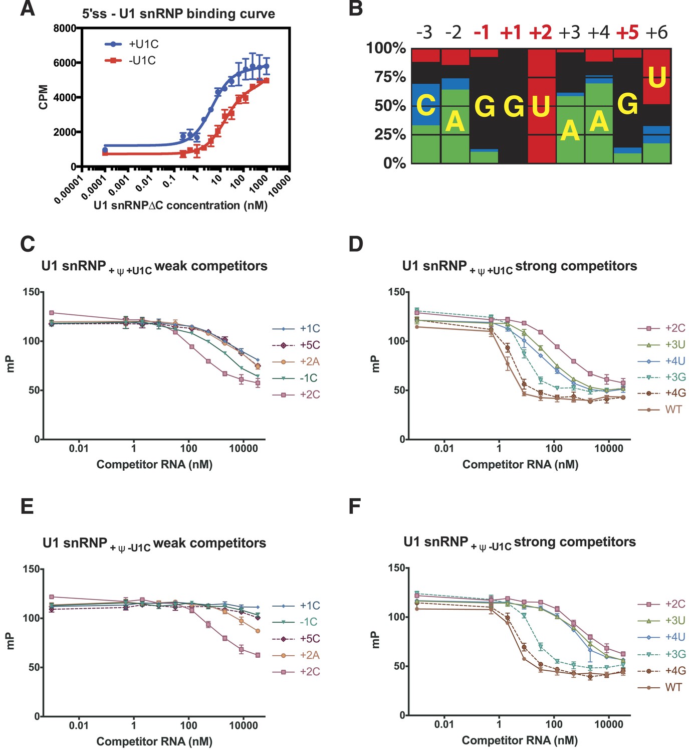
Influence of nucleotide substitutions at the 5′-splice site on U1 snRNP binding.
(A) Filter-binding results for U1 snRNP reconstituted with and without U1-C to [32P]-labelled 5′ splice site oligonucleotide. By curve fitting, the Kd with U1-C is 4.7 ± 0.8 nM and without U1-C is 15.8 ± 2.5 nM. CPM, counts per minute. (B) Nucleotides found at each position of the 5′-splice site of the U2-type introns. Adapted from Roca et al. (2008). A, green; C, blue; G, black; U, red. Numbers for highly conserved positions are highlighted in red. (C) Competition assays of mutant 5′SS RNA binding to U1 snRNP containing U1C and uncapped but fully modified U1 snRNA. The 5′SS oligonucleotide with +1C, +5C, −1C and +2C substitutions compete weakly with the wild type oligonucleotide. In panels C–F, mP is an arbitrary unit of fluorescence polarization and error bars indicate standard error. (D) Competition assay with 5′SS oligonucleotides with +3G, +4G, +3U, +4U substitution and the wild type. 5′SS oligonucleotide with +2C substitution is included for comparison. (E) Same as in B except that U1 snRNP lacks U1-C. (F) Same as in C except that U1 snRNP lacks U1-C.
Tables
Table 1
Crystallographic data collection and refinement statistics
| Minimal U1 | U1A70kF·RNA | |
|---|---|---|
| Data collection | ||
| Space group | P212121 | C2 |
| Cell dimensions | ||
| a, b, c (Å) | 120.4, 172.6, 256.3 | 80.2, 66.6, 93.7 |
| α, β, γ (°) | 90.0, 90.0, 90.0 | 90.0, 111.0, 90.0 |
| Wavelength (Å) | 0.9795 | 1.0332 |
| Resolution (outer shell) (Å) | 69.67 − 3.30 (3.36 − 3.30) | 44.00 − 2.50 (2.64 − 2.50) |
| Unique observations | 80,571 (4538) | 15,967 (2301) |
| Redundancy | 4.6 (4.7) | 3.7 (3.7) |
| Completeness | 99.5 (99.3) | 99.1 (99.4) |
| Rmerge* | 0.153 (0.846) | 0.076 (0.350) |
| Rp.i.m.† | 0.100 (0.534) | 0.047 (0.210) |
| Mn([I]/sd[I]) | 172.1 (2.7) | 11.0 (3.2) |
| Refinement | ||
| Resolution (Å) | 3.30 | 2.50 |
| Number of reflections | 74,960 | 15,164 |
| Rwork/Rfree | 0.209/0.255 | 0.203/0.258 |
| Number of atoms | 26,945 | 3248 |
| Mean B-factor | 99.2 | 49.5 |
| R.m.s.d. bond length (Å) | 0.010 | 0.012 |
| R.m.s.d. bond angles (°) | 1.53 | 1.67 |
| Ramachandran statistics for protein residues ‡ | ||
| In preferred regions | 2534 (96.31%) | 228 (96.61%) |
| In allowed regions | 96 (3.65%) | 8 (3.39%) |
| Outliers | 1 (0.04%) | 0 |
-
*
Merging R factor.
-
†
Precision-indicating merging R factor.
-
‡
Calculated in Coot (Emsley et al., 2010).
Table 2
5′splice site binding
| Oligo name | Sequence* |
|---|---|
| 5ss-F | AGGAAAGUAU-F† |
| WT | CAAAGGUAAGUUGGA |
| −1C | CAAACGUAAGUUGGA |
| +1C | CAAAGCUAAGUUGGA |
| +2A | CAAAGGAAAGUUGGA |
| +2C | CAAAGGCAAGUUGGA |
| +3U | CAAAGGUUAGUUGGA |
| +3G | CAAAGGUGAGUUGGA |
| +4U | CAAAGGUAUGUUGGA |
| +4G | CAAAGGUAGGUUGGA |
| +5C | CAAAGGUAACUUGGA |
-
*
Bold nucleotides highlight the position of mismatch.
-
†
F denotes 3′-fluorescein label.
Download links
A two-part list of links to download the article, or parts of the article, in various formats.
Downloads (link to download the article as PDF)
Open citations (links to open the citations from this article in various online reference manager services)
Cite this article (links to download the citations from this article in formats compatible with various reference manager tools)
Crystal structure of human U1 snRNP, a small nuclear ribonucleoprotein particle, reveals the mechanism of 5′ splice site recognition
eLife 4:e04986.
https://doi.org/10.7554/eLife.04986


