The invariant cleavage pattern displayed by ascidian embryos depends on spindle positioning along the cell's longest axis in the apical plane and relies on asynchronous cell divisions
- Sorbonne Universités, Université Pierre-et-Marie-Curie, CNRS, France
- Institut Jacques Monod, UMR7592 CNRS, France
Figures
Figure 1
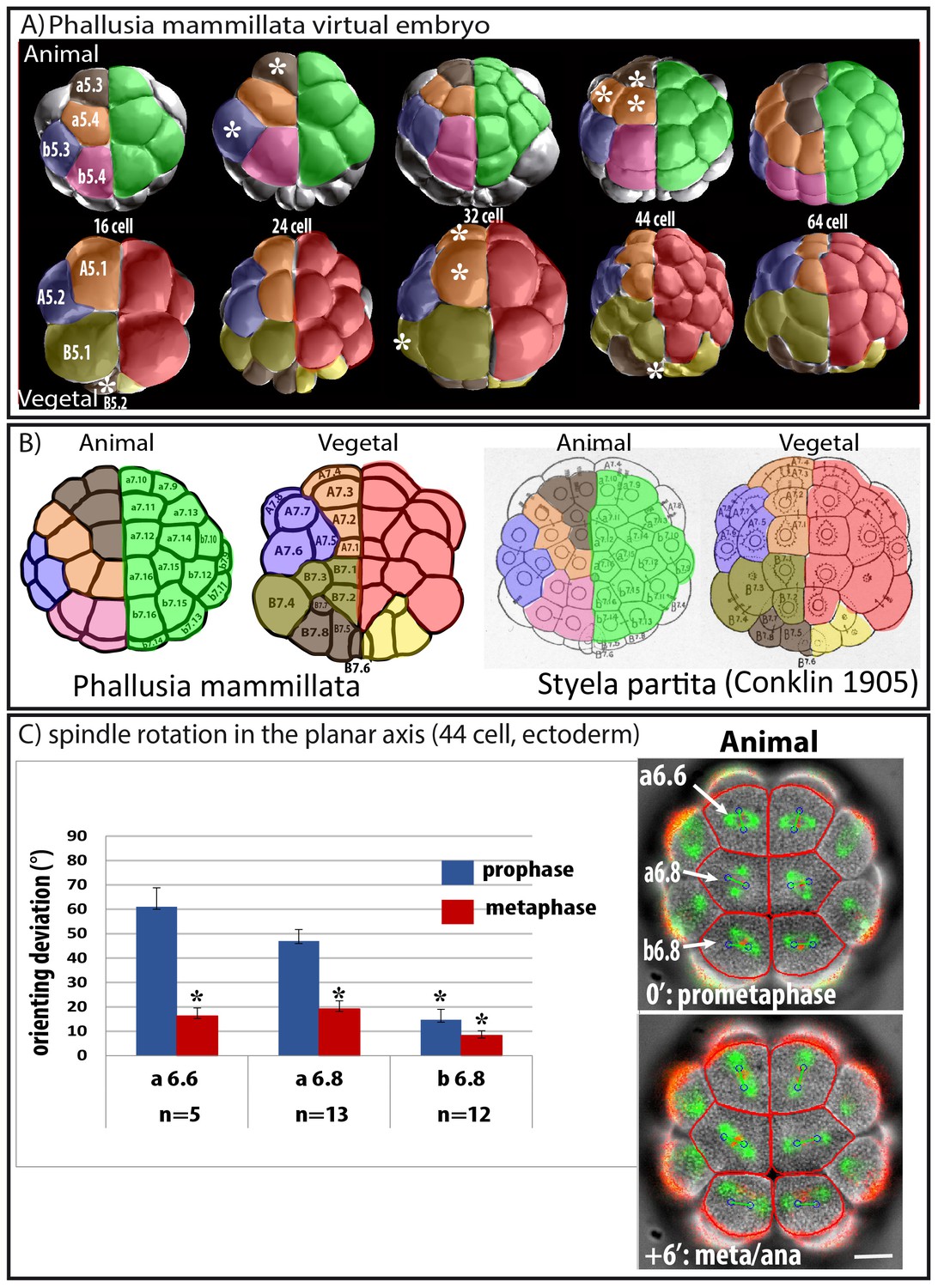
Predicted oriented cell divisions (OCD) in ascidian embryos.
(A) Images taken from virtual Phallusia mammillata embryos (obtained from http://www.aniseed.cnrs.fr/aniseed/download/download_3dve) showing the different embryonic stages. Top row: Animal hemisphere, bottom row: Vegetal hemisphere. The right side of embryos is color coded for germ layers at the 16 cell stage: Ectoderm is in green, endomesoderm in red and germ lineage in yellow. The left side of embryo is color coded according to type of lineages. Lineages displaying square arrangements of 4 cells at 64 cell stage are shown in blue (b5.3, A5.2) and pink (b5.4). Lineages displaying T arrangements are depicted in light (B5.1) and dark (a5.3, B5.2) brown. Lineages displaying linear arrangements of cell are depicted in orange (a5.4, A5.1). (B) Schematic drawing showing 64 cell stage embryos of Phallusia mammillata (left, outlines from an embryo stained with Cell Mask Orange) and of Styela partita (Conklin, 1905). The names of each blastomere are depicted to show conservation of cell positions between the two distant ascidian species. Same color coding as in A. (C) Spindle rotation in the ectoderm (Animal hemisphere) at the 44 cell stage. Time lapse epifluorescence imaging of a P. mammillata embryo expressing MAP7::GFP to monitor mitotic spindles and H2B::mRFP1 to monitor DNA (superimposed on the BF image). In red are the cell’s outline drawn using the BF image during the running of the computational model. Blue circles joined by a green bar represent mitotic spindles predicted by the computational model. Scale bar = 20 µm. Bar graph showing quantification of the angle difference between observed and predicted spindles (orienting deviation). Black asterisks denote statistical difference with the value for a6.6 at prophase/prometaphase (student test; *p<0.05; ***p<0.0001). n represents the number of blastomeres analysed with the computational model.
Figure 2

Changing cell shape in the embryo by compressing embryos or removing cell adhesion.
(A) Compressing embryos: Left: CellMask images of 4 cell-stage embryos in control (4 cell control) or compressed (4 cell compress) conditions. A3, B3 are names of blastomeres, arrowheads indicate the position of the CAB (marking the posterior pole of the embryo). In the images of 4 cell compressed embryos, predicted spindles are shown (blue circles joined by a green line). Scale bar = 30 µm. Middle: sagittal views of control and compressed embryos after 3D rendering on Imaris. Plasma membrane is in green and spindles in red, arrowheads indicate the position of the CAB. Table shows orienting deviation measured in A3 and B3 blastomeres in compressed embryos (n = 8 cells taken from five embryos). Right: Top: CellMask images of control embryo at the 8 cell stage with a Vegetal layer of 4 cells and an Animal layer of 4 cells (same embryo shown). CellMask images of 2 different compressed embryos at the 8 cell stage showing one layer of 8 cells. Arrowheads show the position of the CAB. Scale bar = 30 µm. (B) Culture in Ca2+ free sea water to remove cell adhesion: CellMask image of 4 cell stage embryo cultured in Ca2+ free sea water from the one cell stage. Like in a control embryo, the 4 cells are arranged in one plane. FSW: 8 cell stage embryo cultured in filtered sea water (FSW) exhibiting 2 layers of 4 animal and four vegetal cells (n = 8/8 embryos). Ca-Free SW: 8 cell stage embryos cultured in Ca2+-free sea water from the 2 cell stage exhibiting variable morphologies comprising either wild type morphology (4 animal and four vegetal cells, n = 6 out of 17 embryos) or affected morphologies with 6–5 animal and 2–3 vegetal cells (n = 8 out of 17 embryos) or even one layer of 8 cells (3 out of 17 embryos). Scale bars = 30 µm. (C) DA-aPKC: Image of a 4 cell stage embryo showing embryo morphology (BF image) and spindle positions (imaged with Venus::Tpx2) as well as predicted spindle positions superimposed (blue circles joined by a green line: for those cells where both spindle poles were in the imaging plane. Scale bar = 30 µm. 8 cell stage embryos expressing DA-aPKC::Venus which exhibit variable morphologies comprising either wild type morphology (4 animal and four vegetal cells, n = 2 out of 14 embryos) or affected morphologies with 6–5 animal and 2–3 vegetal cells (n = 10 out of 14 embryos) or 7 and 1 cells (2 out of 14 embryos). Scale bar = 30 µm.
Figure 3
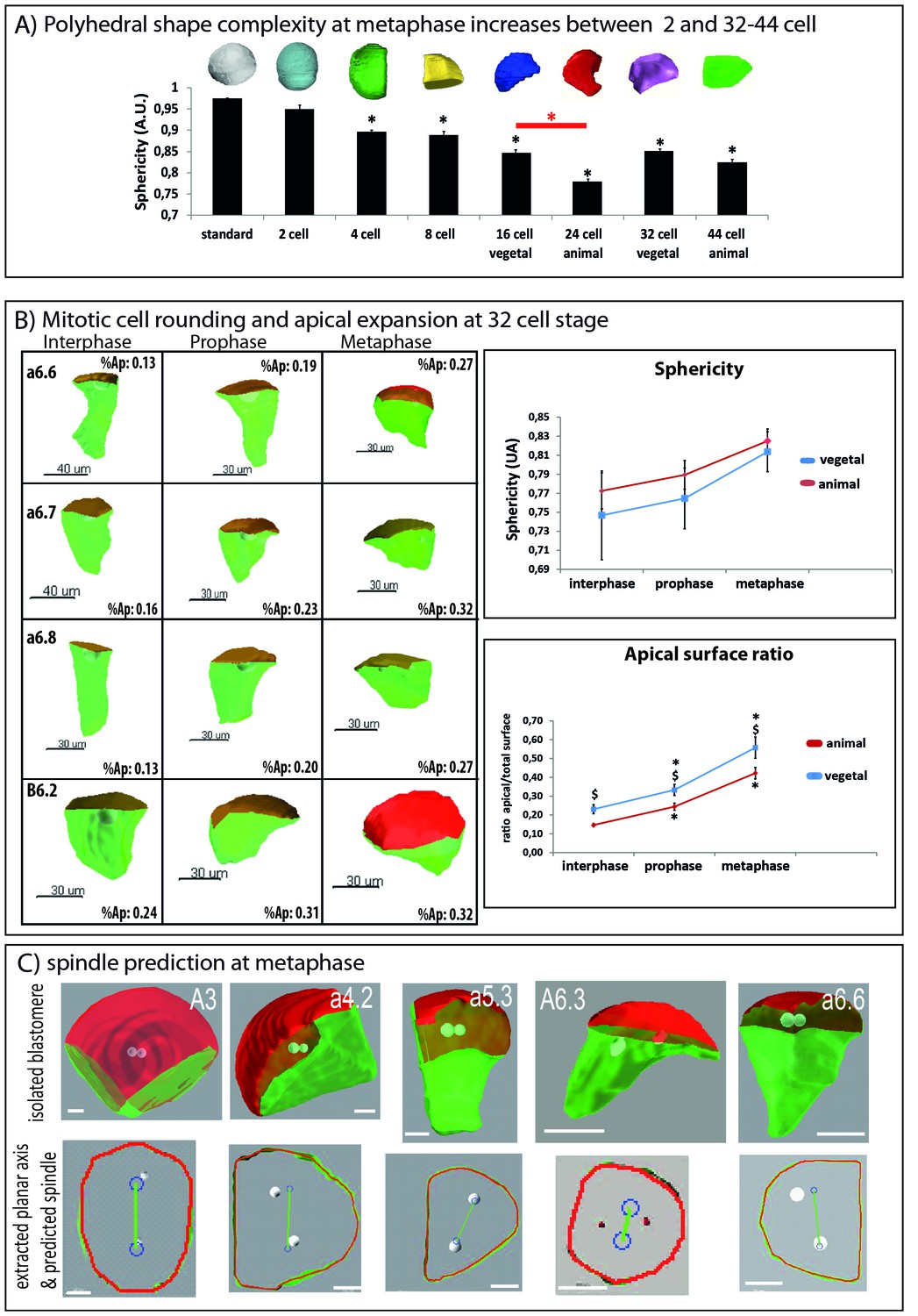
Changes in 3D cell shape during development and during the cell cycle.
(A) Quantification of polyhedral shape complexity of in silico isolated blastomeres at metaphase (using sphericity measurements of Imaris software). While blastomeres at the 2 cell stage have a similar sphericity than a spherical standard (standard: 0.975+/0.001 (n = 4); 2 cell: 0.950 ± 0.010 (n = 4)), from the 4-cell-stage on sphericity significantly decreases compared to standard (p<0.05, black asterisk). Average values are: 4 cell: 0.897 ± 0.013 (n = 8); 8 cell: 0.889 ± 0.009 (n = 8); 16 cell (vegetal): 0.846 ± 0.006 (n = 8), 24 cell (animal): 0.779 ± 0.007 (n = 8), 32 cell (vegetal): 0.851 ± 0.012 (n = 8); 44 cell (animal): 0.825 ± 0.012 (n = 8). Note that animal blastomeres (24 cell stage) have a significantly more complex polyhedral shape than their vegetal counterparts (16 cell) (p<0.05, red asterisk). An example of an in silico isolated blastomere is depicted above each bar of the graph. (B) Quantification of cell shape changes during the cell cycle at the 32–44 cell-stage. Left: 3D views of manually segmented blastomeres at interphase, prophase and metaphase (32 cell stage) showing cell shape changes between interphase, prophase and metaphase (inset: apical surface ratio of cell shown). Green is basolateral and red is apical. Scale bar as indicated. Top right: quantification of cell sphericity at interphase, prophase and metaphase. 6 blastomeres of the animal (red) and vegetal (blue) hemisphere of the 32 cell stage were averaged. The sphericity was significantly higher at metaphase than at interphase (black asterisk, p<0,05). Bottom right: quantification of the apical surface ratio at the same time points. The same blastomeres as in the sphericity graph were used to average apical surface ratio in the animal (red) and vegetal (blue) hemisphere. The apical surface ratio at prophase and at metaphase were significantly higher than at interphase (black asterisks, p<0,05). The apical surface ratio was higher in vegetal blastomeres than in animal ones (§ sign, p<0,05). (C) Pipeline for predicting spindle position using 2D computational model (Minc et al., 2011). See McDougall et al. (2015) for the full protocol of apical plane extraction. Top row shows examples of 3D rendered, in silico isolated blastomeres. Bottom row shows the extracted apical plane of the corresponding blastomeres with spindle predictions (blue circles joined by a green line). Scale bars = 20 µm.
Figure 4
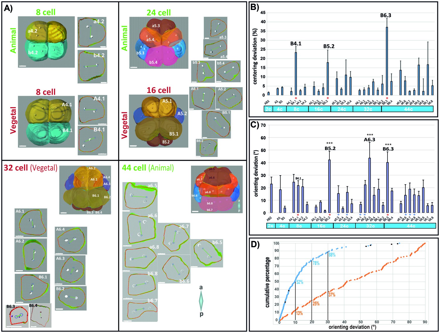
Computational model predicts spindle position and orientation in the apical plane of each blastomere.
(A) 3D views of Phallusia embryos from 8 cell stage to 44 cell stage and extracted apical plane of each blastomere. Observed spindle poles are depicted by white circles/balls. Predicted spindles are depicted with blue circles joined by a green line. The red outline of each cell is the shape used by the computational model to predict spindle position. a=anterior, p=posterior, scale bars are all 20 µm. Lineages are color coded like in Figure 1. (B) Mean centering deviation in each blastomere. n = 6 cells analysed for each blastomere except A6.4 (n = 4); B6.1 (n = 5); a6.7 (n = 4), b6.5 (n = 4). Red asterisk denote cells undergoing unequal cleavage. (C) Mean orienting deviation in each blastomere. n = 6 cells analysed for each blastomere except A6.4 (n = 4); B6.1 (n = 5); a6.7 (n = 4), b6.5 (n = 4). Red asterisks denote cells undergoing unequal cleavage. Blue asterisks denote blastomeres undergoing OCD. Triple black asterisks denote that orienting deviation in the grouped B5.2, A6.3, and B6.3 cells are statistically greater than those in other lineages (Wilcoxon rank sum test with continuity correction, p-value=4.789*10−7). (D) Quantification of orienting deviation: cumulative percentage graph of measured data (blue dots, n = 149 cell divisions, black dots denote the six A6.3 cells analysed) and randomly generated data (orange dots, n = 149). The measured data are not uniform and significantly different from the random data (One-sample Kolmogorov-Smirnov test, p<2.2*10−6). The numbers indicated under each graph is the proportion of cells with orienting deviations under the considered threshold (10°, 20, and 30°).
Figure 5
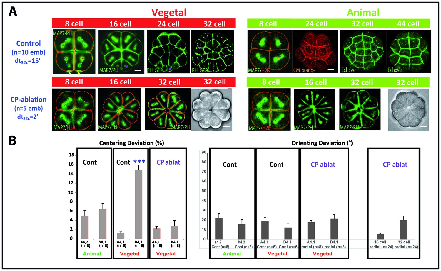
Removing the maternal CAB prevents unequal cleavage and radializes embryos.
(A) Images showing embryonic morphology and cell shapes in Control (top row) and CP-ablated (bottom row) embryos. Top row: Images showing mitotic spindles (MAP7::GFP) and cell membranes (PH::GFP, CM-orange: Cell Mask Orange; Ech::Ve: Echinoid::Venus). Scale bar = 15 µm. Animal hemisphere (An) is depicted in green while the vegetal hemisphere (Veg) is depicted in red. Purple asterisks indicate unequal cell division in the germ line. Bottom row: images showing mitotic spindles and cell membranes (MAP7::GFP and PH::GFP) in radialised embryos in which the contraction pole (CP) was removed (CP-ablation). These embryos (n = 5) are completely radialised and do not bear small cells in the vegetal posterior pole of the embryo. Scale bar = 15 µm. (B) Left: Quantification of centering deviation showing that it is less than 10% in a4.2, b4.2 and A4.1 blastomeres whereas it is over 10% in B4.1 of control embryos. In CP-ablated embryos centering deviation is not affected in A4.1 but is decreased in B4.1. Triple asterisk indicates a significant difference with A4.1 (student, p=0.00004). Right: Quantification of orienting deviation showing that it is below 30° in both control and CP-ablated embryos at the 8 cell stage (a4.2, b4.2, A4.1, B4.1) and at the 16 and 32 cell stages in CP-ablated embryos.
Figure 6
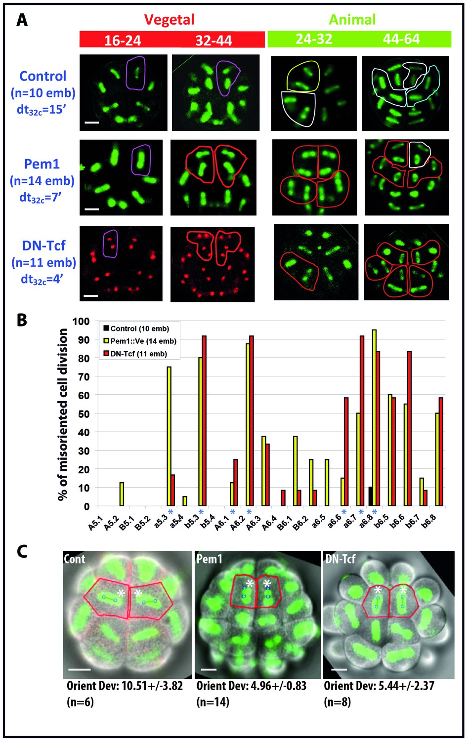
Impact of zygotic transcription on the invariant cleavage pattern.
(A) Images showing metaphase spindle (green) and nuclei (red) in control, Pem1::Ve and DN-Tcf expressing embryos. Unaffected cell divisions are surrounded by a colored line (in control and manipulated embryos). Misoriented cell divisions are surrounded by a red line. Scale bars = 20 µm. dt32c indicates the difference in timing of mitotic entry between animal and vegetal hemispheres at the 32–44 cell stage. (B) Graph plotting the incidence of misoriented cell divisions in control (black bars), Pem1::Ve (yellow bars) and DN-Tcf (red bars) embryos. Blue asterisks denote blastomeres undergoing OCD. (C) Images showing embryonic morphology in the ectoderm (animal) at the 32–44 cell stage. Blastomeres with asterisks are a6.8 for which cell outline (in red) and spindle prediction (blue circles joined by a green bar) are depicted. Orienting deviation in a6.8 blastomeres displaying OCD in control embryos and misoriented cell divisions in a6.8 blastomeres in Pem1 and DN-Tcf embryos are indicated under the images. n indicates the number of a6.8 blastomeres analysed. Scale bars are 20 µm.
Figure 7
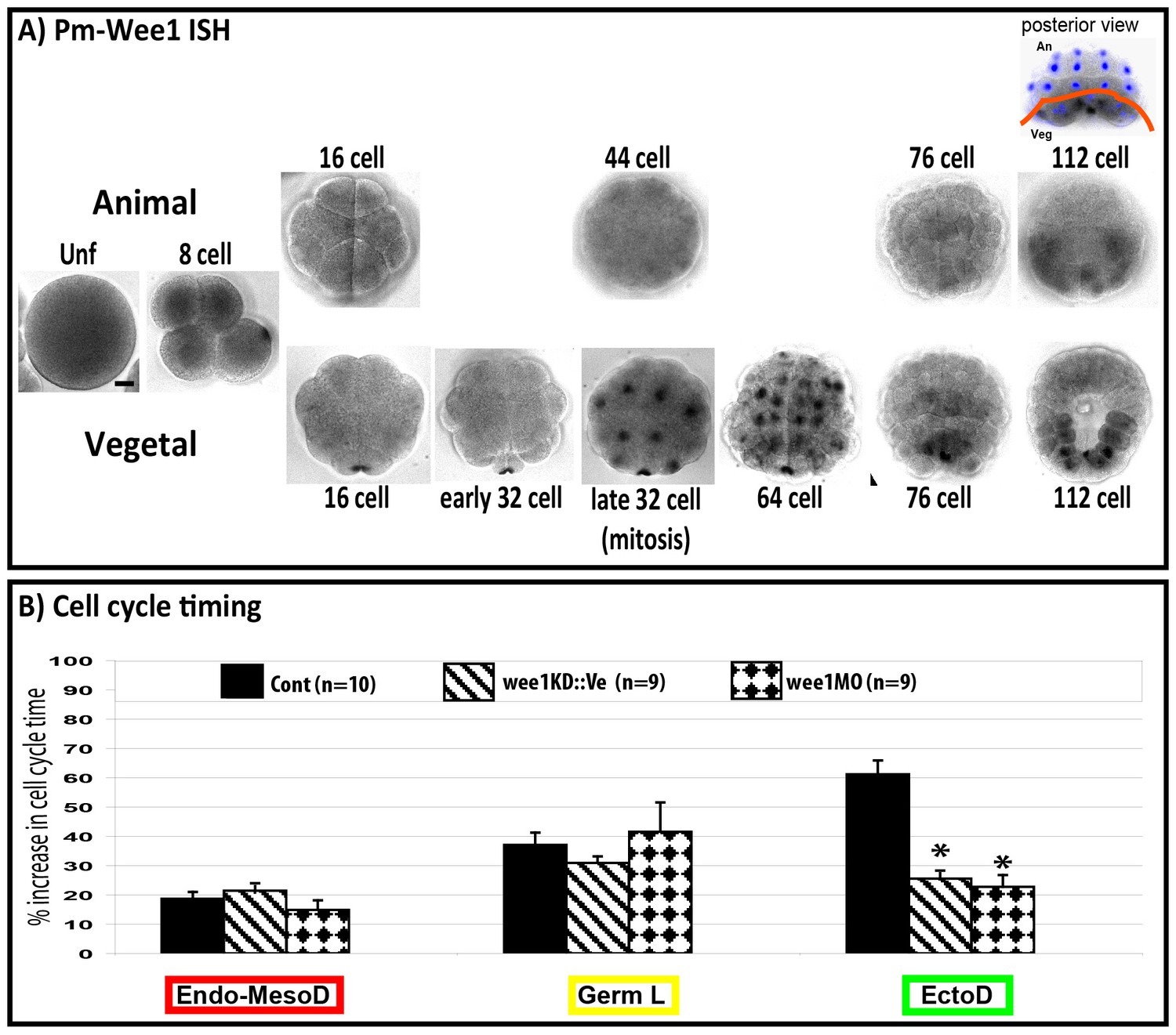
Inhibiting cell cycle asynchrony in the ascidian blastula.
(A) Images showing in situ hybridizations of Pm-Wee1 from the unfertilized egg (Unf) to the late 112 stage. Wee1 is expressed in the unfertilized oocytes where it is slightly enriched in the vegetal cortex of the egg. Then a maternal signal can be observed in the early stages with a specific enrichment in the CAB region hosting the germ plasm. Zygotic Wee1 is expressed in the endoderm precursors from the late 32 cell stage to the 76 cell stage and in the muscle precursor from the 112 cell stage (i.e., just before they gastrulate). In some images Hoechst staining of nuclei is shown in blue. Scale bar is 20 µm. (B) Quantification of cell cycle length at the 16–32 cell stage (MBT, cell cycle 5) in manipulated embryos: control embryos (black bars, n = 10), embryos expressing Wee1KD::Ve (stripped bars, n = 9), embryos injected with wee1 MO (diamond bars, n = 9). wee1KD and wee1 MO both speed up the ectoderm cells (EctoD) without affecting the endomesoderm (Endo-MesoD) or the germ line (Germ L). % increase in cell cycle time relative to cell cycle timing at the 8 cell stage. A 20% increase means that the cell cycle timing has increased by 20% compared to the previous cell cycle at 8 cell stage (see Dumollard et al., 2013 for details). Triple black asterisks indicate p=0.0003 for wee1KD and p=0.000009 for wee1MO.
Figure 8

Impact of cell cycle asynchrony on the invariant cleavage pattern.
(A) Images showing metaphase spindles in control and wee1 MO injected embryos (top two rows) or showing nuclei in wee1KD::Ve and control embryos (bottom two rows). Unaffected cell divisions are surrounded by a colored line in control embryos. Misoriented cell divisions occurring in manipulated embryos are surrounded by a red line. Scale bar = 20 µm. dt32c indicates the difference in timing of mitotic entry between animal and vegetal hemispheres at the 32–44 cell stage. (B) Graph plotting the incidence of misoriented cell divisions in control (black bars), wee1KD (pink bars) and wee1 MO (purple bars) injected embryos. Blue asterisks denote blastomeres undergoing spindle rotation, green asterisks indicate daughters of b5.3 (undergoing spindle rotation). Inset: Images showing embryonic morphology in the ectoderm (animal) at the 32–44 cell stage. Blastomeres with asterisks are a6.8 for which cell outline (in red) and spindle prediction (blue circles joined by a green bar) are depicted. Orienting deviation in a6.8 blastomeres displaying OCD in control embryos (n = 6 cells) and misoriented cell divisions in wee1-KD (n = 8 cells) embryos is indicated in the images. Scale bars are 20 µm.
Videos
Video 1
Spindle rotation in the ectoderm in cells undergoing oriented cell divisions.
Movie showing live imaging of a Phallusia mammillata embryo injected with RNAs coding for MAP7::GFP (in green) and H2B::mRfp1 (in red). (z-stacks taken 2 min apart). View of the ectoderm showing mitoses of 24–32 cell stage and 44–64 cell stage. Spindle rotation is clearly visible in six blastomeres at mitosis 44–64 cell stage (a6.6; a6.7; a6.8).
Download links
A two-part list of links to download the article, or parts of the article, in various formats.
Downloads (link to download the article as PDF)
Open citations (links to open the citations from this article in various online reference manager services)
Cite this article (links to download the citations from this article in formats compatible with various reference manager tools)
The invariant cleavage pattern displayed by ascidian embryos depends on spindle positioning along the cell's longest axis in the apical plane and relies on asynchronous cell divisions
eLife 6:e19290.
https://doi.org/10.7554/eLife.19290


